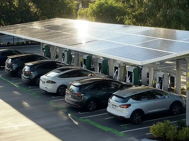
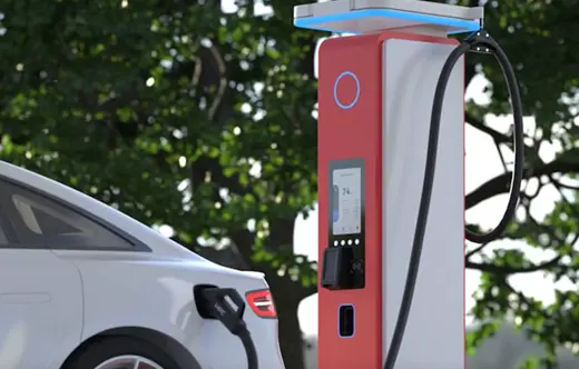
The right BESS-PLUS 500GP configuration is the one built around a defined operating duty, not around a model name or headline battery figure. A peak-shaving project needs a verified demand profile and discharge window. Solar self-consumption needs generation and load data on the same time base. Backup service adds islanding, transfer, essential-load and restart requirements. An EV charging site is driven by short power peaks, charger scheduling and the grid connection limit.
Commercial interest in service-based storage has grown since ABB introduced BESS-as-a-Service for commercial and industrial energy storage. That business model changes ownership and lifecycle responsibility; it does not remove the need to define power, usable energy, controls, safety provisions and site interfaces. Whether a system is purchased, financed or supplied as a service, the equipment still has to perform a measurable duty at a real point of connection.
Start With the Operating Objective, Not the Battery Cabinet
A battery energy storage system can serve several objectives, but those objectives do not necessarily require the same design. The project team should identify one primary duty and rank any secondary duties. Otherwise, the supplier may size the battery for one use while the economic model assumes another.
For example, a system selected for one daily peak-shaving cycle may not have enough reserved energy for an unplanned outage. A backup-oriented reserve can also reduce the energy available for tariff shifting. The conflict is not theoretical: both services draw from the same usable state-of-charge window. The energy-management strategy therefore belongs in the configuration discussion from the beginning.
Dingsheng lists several systems in its commercial and industrial energy storage range. Product-family screening is useful, but project sizing should begin with the load and operating objective rather than a catalog capacity comparison.
| Primary application | Data that defines the duty | Configuration consequence | Evidence to request |
| Peak shaving | Interval load data, tariff window, demand threshold and expected cycle frequency | Continuous power and discharge duration must cover the shape of the peak, not only its maximum value | Dispatch simulation, usable-energy basis and assumed operating window |
| Solar self-consumption | Time-aligned PV generation, facility load and export limits | Charge power must absorb the usable surplus, while energy capacity must carry it to the required load period | Representative-day energy balance and curtailment assumptions |
| Engineered backup | Essential-load schedule, interruption tolerance, outage duration and load-starting behavior | Reserve policy, islanding method, grid-forming capability and protection coordination may become decisive | Single-line diagram, operating sequence and witnessed mode-transfer test plan |
| EV charging support | Charger ratings, arrival pattern, dwell time, simultaneity and grid import limit | Power response and control integration can matter more than a large nominal energy figure | Charging-load simulation, EMS interface list and point-of-connection limit |
Power and Usable Energy Solve Different Parts of the Problem
Power, expressed in kW or MW, describes the rate at which the system can charge or discharge. Energy, expressed in kWh or MWh, describes how long that power can be sustained. A facility needing 400 kW for fifteen minutes presents a different duty from one needing 100 kW for four hours, even though the simplified energy arithmetic is similar.
The procurement value lies in matching both dimensions to the load profile. Oversizing energy while undersizing power leaves the system unable to clip the required peak. Oversizing power without enough usable energy produces a strong initial response that ends before the operating window closes. This is why a single capacity label cannot define application fit.
Usable energy also needs a stated basis. Gross installed energy, beginning-of-life usable energy and warranted end-of-life usable energy are not interchangeable. State-of-charge limits, temperature, auxiliary consumption and degradation assumptions change what reaches the project load. A comparable proposal states the measurement point and the operating conditions behind the number.
Build the Configuration From a Time-Series Load Profile
Monthly electricity bills can identify tariff exposure, but they rarely show the shape of a demand event. Interval data reveals when the peak occurs, how quickly it rises, how long it lasts and whether it repeats. Fifteen-minute data is a common starting point for commercial analysis; sites with sharp charging or process loads may need finer resolution.
For peak shaving, the project team can set a target grid-import limit and calculate the battery power needed whenever facility demand exceeds it. Integrating the area above that limit estimates the energy required for each event. Repeating the calculation across representative operating days exposes seasonal and production-related variation.
Solar projects need the same discipline. A daily total for PV generation and a daily total for consumption can look well matched while occurring at different times. Time-aligned curves show how much surplus can actually charge the battery and when stored energy will be discharged. Without that alignment, the expected self-consumption gain may be overstated.
Backup Duty Changes the Electrical Architecture
Stored energy alone does not prove that a grid-connected BESS will supply loads during an outage. The design must define how the installation separates from the grid, which bus remains energized, what establishes voltage and frequency, how protection behaves in islanded operation and how loads are picked up.
Motor starting, transformer inrush and step changes in load can set the inverter requirement even when the steady-state essential load is modest. Cooling, controls, communications, switchgear trip circuits and other dependencies also belong in the essential-load map. A process can still stop if the main machine is backed up but a necessary auxiliary is not.
The useful acceptance evidence is an operating sequence tied to the approved single-line diagram. It should state normal-grid behavior, outage detection, isolation, islanded operation, low-state-of-charge response and grid restoration. Where uninterrupted power is required, the permitted transfer time and power-quality limits must be specified; a BESS should not be assumed to perform as a UPS without verified system-level behavior.
PCS, EMS and Site Interfaces Must Be Defined Together
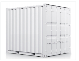
The power conversion system determines the electrical conversion boundary and supported operating modes. The energy management system decides when the battery charges or discharges, but it relies on accurate measurements, communication links and permissions. Site switchgear and protection determine whether those commands can be executed safely at the point of connection.
Treating these packages as independent purchases creates predictable interface gaps. A control strategy may require a meter that is outside the supplier scope. A transformer ratio may not suit the PCS voltage. Protection settings may be unavailable because the short-circuit study is incomplete. A remote dispatch function may depend on a protocol or network responsibility that no party has accepted.
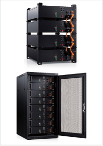
The BESS-PLUS 500GP product reference identifies the E-MATE 500GP family and battery-module information. Before treating that reference as a project configuration, request the complete offered boundary: rated and usable energy, charge and discharge power, PCS, EMS, protection, thermal management, enclosure, fire-safety provisions, auxiliary supply, transformer or switchgear interface, communications and commissioning scope.
Site Conditions Can Reduce an Apparently Suitable Rating
Ambient temperature, altitude, dust, humidity, corrosion exposure, drainage, flood level and access all influence equipment selection. Thermal management consumes energy and may limit available power in severe conditions. Altitude can affect cooling and insulation design. Restricted access can change enclosure segmentation, lifting plans and maintenance clearances.
These conditions should be written into the specification rather than left for a late site survey. IEC 62933 addresses grid-integrated electrical energy storage at the system level, including safety considerations and environmental effects, but the applicable national electrical rules, fire requirements, grid code and authority approvals still depend on the destination. A component certificate cannot establish project compliance by itself.
Request a compliance matrix that maps the offered configuration to the project requirements and identifies exclusions. The matrix should distinguish equipment evidence from installation responsibilities. This prevents a general certificate, enclosure rating or subsystem test from being mistaken for acceptance of the complete installation.
Use an Operating-Mode Matrix to Resolve Competing Priorities
A useful configuration document states what the system does in each operating condition. Normal tariff optimization, a demand peak, high PV production, an approaching storm reserve, a grid outage and system recovery may require different state-of-charge targets and control priorities.
That matrix also reveals whether two promised services can occur at the same time. A battery cannot commit its full usable energy to both energy arbitrage and backup reserve. Nor can it discharge for peak shaving while maintaining the same headroom for absorbing unexpected solar surplus. The contract should define which objective takes priority and how the EMS changes modes.
Performance guarantees should use the same boundaries. If the project is judged at the grid connection point, auxiliary consumption and conversion losses cannot be ignored. If availability excludes planned maintenance or grid outages, those exclusions should be visible. Clear definitions make later acceptance testing far more useful than a broad statement that the system is “500GP configured.”
What a Decision-Ready BESS RFQ Should Contain
A workable RFQ begins with project data rather than a request for “one BESS-PLUS 500GP.” Include the installation country and site conditions, point-of-connection voltage, single-line diagram, interval load data, renewable-generation profile, primary and secondary operating objectives, required power, target duration, essential-load schedule, reserve policy, expected cycles, communication requirements and intended delivery boundary.
Ask the supplier to return a configuration schedule that identifies the offered power and usable-energy basis, operating limits, battery and PCS boundary, EMS functions, auxiliary loads, protection interfaces, thermal and fire-safety scope, documentation, factory tests, site tests, commissioning responsibilities and declared deviations. Optional items should be separated from the base offer so technical scope can be normalized before price and delivery are compared.
Once those inputs are assembled, submit them through Dingsheng’s project specification inquiry form. The objective of the first exchange is not a headline price. It is a configuration that can be traced from the site duty to the equipment scope and then verified during acceptance.